
A-B-C Blog

How to Choose a Pneumatic Conveying Blower?

Choosing a Pneumatic Conveying Blower is not simply a matter of selecting the largest motor or the highest advertised airflow. The blower must suit the material, conveying distance, pipe layout, and required production rate. A light plastic pellet behaves differently from a dense mineral powder. Even a small change in moisture or particle size can affect how material moves through a line.

Start with the system’s required airflow and pressure, then check how those figures change across actual operating conditions. Consider pipe diameter, bends, pickup points, filters, elevation, and the pressure losses each component creates. Blower type matters too: positive displacement and centrifugal designs have different operating characteristics. Neither is automatically the better choice. Noise, temperature, energy use, maintenance access, and available installation space also deserve attention. Small details matter.

Reliable sizing depends on sound data. Record the material’s bulk density and flow behavior, and ask the supplier to review the full system duty rather than a single headline number. Early estimates are useful, but they are not a substitute for measured operating information. That can be an uncomfortable limitation when a project is still being planned. Still, stating assumptions clearly is better than hiding uncertainty. This guide explains the questions to ask, the specifications to compare, and the trade-offs to examine before choosing a Pneumatic Conveying Blower.
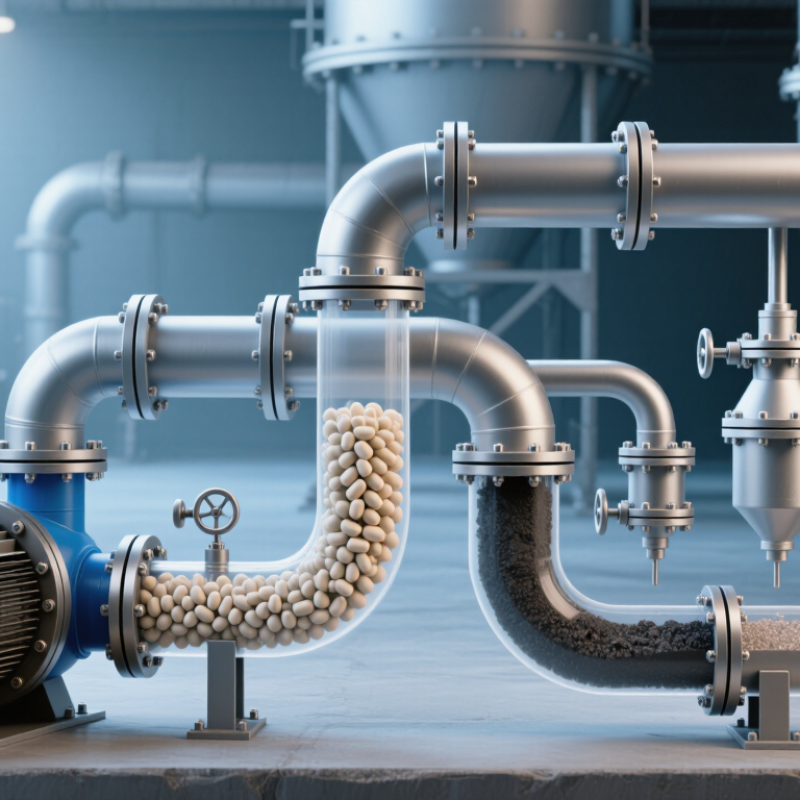
How to Choose a Pneumatic Conveying Blower?

Define Conveying Phase: Dilute Flow Typically Runs at 15–30 m/s

Dilute-phase conveying keeps particles suspended in fast-moving air. A practical starting range is 15–30 m/s, as stated in the subtitle, but it is not a universal setting. David Mills’ Pneumatic Conveying Design Guide, 3rd edition (2016), discusses velocity as a key design variable in dilute-phase systems.

The right value depends on particle size, density, moisture, pipe diameter, and route length. A fine, dry powder may travel differently from coarse granules. That matters. Too little velocity can let material settle, especially after elbows or during startup. Excessive velocity can increase pipe wear, particle damage, and blower energy use.

Choose the blower around the required airflow and pressure at the conveying point, not just its headline power rating. Klinzing and co-authors’ Pneumatic Conveying of Solids, 3rd edition (2010), also treats conveying behavior as dependent on material properties and system conditions.

This is why a trial run or measured operating data can be more useful than a tidy estimate alone. Not always. Check the pressure drop across the full line, including bends, pickup points, and filters. Then confirm that the blower can maintain the target velocity under real loading.

Leave room to adjust: actual material can behave differently from a sample, and the first calculation may need revision.

Estimate Airflow from Throughput, Pipe Size, and Solids Loading Ratio

Begin with the solids throughput, stated as mass per hour, and confirm whether it is a steady rate or a short peak. A feeder delivering 2,000 kilograms per hour needs a different air estimate from one that briefly surges above that rate. Check the material’s bulk density and moisture too. Small changes can alter how it flows.

Choose a solids loading ratio: the mass of solids carried per mass of air. Divide the solids mass rate by this ratio to estimate the required air mass rate. For example, a ratio of 10 means roughly 200 kilograms of air per hour for 2,000 kilograms of solids. Convert that air mass to volume using the blower’s operating pressure and temperature, not just room conditions.

Now check the pipe diameter and resulting conveying velocity. A larger pipe may reduce friction, but it can also let particles settle if airflow is too low. A smaller pipe raises velocity and pressure loss. Include pipe length, bends, pickup points, and filters in the pressure estimate. This calculation is a starting point, not a guarantee. Real powders can behave unpredictably. Compare the estimate with conveying trials, pressure readings, and signs of settling or excessive wear, then adjust the loading ratio and airflow with care.

Calculate Required Pressure; Roots Blowers Commonly Deliver up to 1 bar(g)

Selecting a pneumatic conveying blower starts with the pressure the system actually needs—not the highest pressure available. Estimate pressure losses across the pickup point, pipe runs, bends, elevation changes, and filters. Then check the material, conveying rate, and operating mode; dense-phase service may need different conditions from dilute-phase conveying. Roots blowers commonly deliver up to about 1 bar(g), but this is a general range, not a guarantee for every model or duty. Confirm the required differential pressure against the supplier’s performance curve.

Pressure margin matters. Too little can reduce throughput or leave material in the line. Too much can waste energy and raise discharge temperature. The U.S. Department of Energy’s Improving Compressed Air System Performance sourcebook reports that a 2 psi increase in compressor discharge pressure can raise energy use by about 1% under certain conditions. That figure is not a blower-sizing rule, but it shows why pressure should not be set casually. Real systems are messier than a neat calculation.

Tips: Measure pressure at the conveying line, including filter pressure drop. Check the worst-case material and flow rate, not just average operation. Leave a practical margin, then verify it during commissioning. A margin that is too generous can quietly become a permanent energy penalty.

How to Choose a Pneumatic Conveying Blower

Compare indicative pressure ranges before selecting a blower for your conveying system.

Dilute-phase systems commonly operate at lower pressures, while dense-phase systems may require substantially higher pressures. Roots blowers commonly deliver up to about 1 bar(g), depending on the equipment and operating conditions. These ranges are indicative, not design limits; confirm the required pressure from a system assessment and the equipment specifications.

Select Blower Type by Duty: Roots, Screw, or Centrifugal

Choosing a pneumatic conveying blower starts with the duty, not the machine’s label. Roots blowers use rotating lobes to deliver steady, high-volume airflow at moderate pressure. They are a practical fit for many dense-phase or dilute-phase systems, but their pulsation can create noise and vibration. Allow space for suitable silencers and check the pressure requirement against the blower curve.

Screw blowers also use positive displacement, with smooth, continuous airflow and strong efficiency in sustained service. They can suit systems that need higher pressure or run for long hours. Their purchase and maintenance costs may be higher, so compare total operating needs, not energy figures alone. Small details matter. Dust, inlet temperature, and filter condition can change performance.

Centrifugal blowers suit high airflow at relatively low pressure, especially where conveying demand stays stable. Their output responds to system resistance, so a long pipe, extra bends, or a loaded filter can shift the operating point. Not always obvious. Match the blower to the material, route length, conveying rate, and pressure losses, then verify the selection using actual system data. A tidy catalogue comparison can still miss a troublesome elbow or future capacity change. Recheck those assumptions before sizing.

Verify Power, Discharge Temperature, Filtration, and Noise Requirements

How to Choose a Pneumatic Conveying Blower?

Choose a blower by matching its operating point to the conveying system, not by motor power alone. Estimate the required airflow and pressure using material density, line length, pipe diameter, and bends. Check the blower curve at that point, then allow a practical power margin. Too much margin can waste energy; too little may leave material settling in the line. Dust matters.

Check discharge temperature during continuous operation, especially if the material or downstream equipment is heat-sensitive. A temperature reading at startup may not reflect a fully loaded system. Confirm the blower’s filtration needs with the material’s dust level and the site’s environment. A clogged inlet filter can reduce airflow and raise operating strain. Also consider noise at the operator’s position, not only beside the machine. Enclosures can help, but they may restrict cooling if poorly designed.

Tips: Ask for power, temperature, and noise data at your expected duty point. Verify filter pressure drop, and leave room for routine maintenance. Real systems rarely behave exactly like the first estimate.

How to Choose a Pneumatic Conveying Blower? - Verify Power, Discharge Temperature, Filtration, and Noise Requirements

Selection Dimension What to Establish Indicative Screening Data What to Verify Before Purchase
Conveying airflow Required air volume at the blower inlet, conveying method, material throughput, pipeline layout, and operating conditions. Industrial conveying systems may require anything from hundreds to several thousand cubic metres per hour. Final airflow depends on the material, pipe diameter, conveying distance, and solids loading. Confirm whether the quoted flow is stated at inlet conditions or at another reference condition. Check the operating point against the system calculation, not just the blower’s maximum flow.
Discharge pressure or vacuum Required pressure rise for positive-pressure conveying, or required vacuum level for a vacuum system, including pipeline and equipment losses. As an initial screening range, positive-pressure systems can operate at tens of kilopascals gauge; some applications require higher pressure. Vacuum systems are specified as pressure below atmospheric pressure and must remain within the blower’s rated limits. Include pressure losses across pipes, bends, filters, valves, feeders, and receivers. Specify pressure units and whether values are gauge or absolute.
Drive power Motor rating required at the selected flow and pressure, with allowance for operating conditions and starting requirements. A first-order air-power estimate is airflow multiplied by pressure rise. For example, 2.0 m³/s at 60 kPa represents 120 kW of air power; at an assumed overall efficiency of 65%, estimated shaft power is about 185 kW. This is a screening calculation, not a final motor selection. Request the manufacturer’s absorbed-power curve at the actual operating point. Check motor service factor, electrical supply, altitude, ambient temperature, starting method, and any required operating margin.
Discharge air temperature Maximum acceptable outlet temperature for the conveyed material, nearby equipment, and process safety requirements. Blower discharge air can become substantially warmer than inlet air, especially at higher pressure ratios or during hot-weather operation. Temperature rise is operating-point and machine dependent; a universal outlet-temperature value is not reliable. Obtain predicted outlet temperature at the highest expected inlet temperature and full-load condition. Confirm whether cooling, temperature monitoring, or a high-temperature shutdown is required.
Inlet filtration Required protection from dust and particles, filter location, acceptable pressure drop, and maintenance interval. Filter media and particle-retention rating must suit the blower maker’s requirements and the site environment. A fine intake filter may be appropriate in dusty locations, but excessive filter restriction can reduce delivered flow and increase operating stress. Confirm the specified filtration rating and clean/dirty pressure-drop limits with the equipment supplier. Provide a differential-pressure indicator and safe access for inspection or replacement where needed.
Noise level Permitted sound level at the relevant measurement position and the site’s occupational-noise requirements. Unattenuated industrial blower packages can exceed 85 dB(A) near the equipment; actual sound levels vary with blower type, speed, inlet and discharge piping, and enclosure design. Any limit should state the distance and measurement conditions. Request sound data for the complete package, including silencer and enclosure if supplied. Specify the required dB(A) level, measurement distance, and whether the value applies at full load.
Material and conveying mode Material bulk density, particle size, abrasiveness, moisture, temperature sensitivity, and whether the system is dilute-phase or dense-phase. These properties influence the required airflow, pressure, wear protection, and risk of plugging or product degradation. No single blower operating point suits all materials. Provide representative material data and the expected conveying rate. Confirm compatibility of wetted materials, seals, and any required contamination controls.
Operating environment Ambient temperature, elevation, indoor or outdoor installation, dust exposure, and duty cycle. High ambient temperature and elevation can affect air density, cooling, available performance, and motor capacity. Continuous-duty service may require different selection margins from intermittent operation. State minimum and maximum ambient temperatures, site elevation, operating hours, and enclosure requirements. Verify performance and motor suitability for the actual site conditions.
Controls and protection Required monitoring, alarms, interlocks, and shutdown conditions. Common provisions include discharge-temperature monitoring, pressure or vacuum indication, filter differential-pressure monitoring, and motor overload protection. Define alarm and trip setpoints with the equipment supplier and integrate protections with the conveying system controls. Do not use protective devices as substitutes for correct sizing.

Note: The ranges and example calculation are for preliminary screening only. Final blower selection should be based on the system design, site conditions, and a performance proposal at the required operating point.